What: We’re Unusual? So, it turns out that not only is the house unorthodox, but so are our procedures. It seems that most builders place and finish the concrete floors in the basement and garage after the roof is on. We’d like to do it before the framing for a couple reasons:
- it gives us a hard, clean surface to work on; and
- it allows us to frame a couple walls in the basement mechanical room so we can mount the load centre (“breaker box”). The latter then allows us to bring power in early and move away from the generator and its GHG emissions.
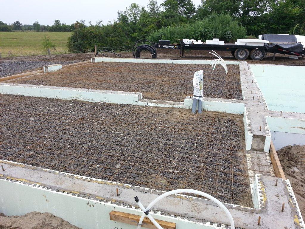 Preparing the Basement Floors – Since the backfill we’ve been working primarily in the basement area where we’ve done the following:
- Leveled the crushed stone.
- Placed high density EPS insulation under where the metal posts will hold up the main beam. Between the posts and the EPS are reinforced concrete footings. The EPS will prevent thermal bridging between the footings and the earth.
- Placed two layers of EPS insulation under the basement slab; one 8” layer then another of 4”. Seams of each layer were offset to reduce convection losses. Sprayfoam was used for large gaps but care was taken not to put it in before the EPS was mechanically fixed in-place. Regular expanding foam, and even low-expansion foam, has a tendency to move even the large blocks of EPS, so use of expanding foams was carefully controlled. As a note to others using spray urethane foam, water helps it cure. We kept a spray bottle of water nearby to get better performance.
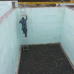
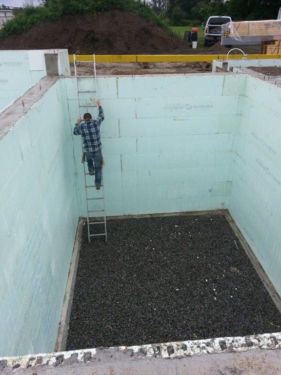
- Our design calls for an 8” layer of EPS up the walls (on top of the 2 5/8” of EPS in the ICF). It was applied at this stage. Later, there will be even more basement wall insulation when the 2”x4” stud walls are built to sit on the slab and get their mineral wool cavity fill.
- Before the slab and stud walls, however, comes the vapour / air barrier. In this case we’re using standard 6 mil poly, taped. Where there are pipe and conduit penetrations, rectangles of EDPM (sheet rubber) that were used to provide a good, tight seal; holes were cut into the EPDM that were about half the size of the pipe, placed around the pipes, then taped to the poly.
- Concrete footings with rebar were placed including anchor bolts for the steel posts.
- Steel mesh for concrete floor was placed and tied together.
- Hydronic heating / cooling tubes were laid and tied to the steel mesh. If I get feedback showing interest in it, I could post another entry on how our hydronic system – which is also atypical – is designed to optimize broader system efficiency (including solar collectors, storage tanks, and pumping energy).
With the basement floors preparations complete, we then focused our attention 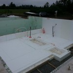 on the main floor’s support beam. Three layers of LVL (laminated veneer lumber) were placed, straightened and nailed together. We then wedged the steel posts into place, plumbed and then fixed them to the beam. A high-strength concrete grout was placed under the posts to make a firm, distributed cont
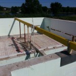 act between post and footing, then the posts were tightened down firmly to the anchor bolts. The posts are now ready to have the floors poured around them to completely anchor them in-place.
Tanks – Once preparations for the floor wer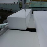 e complete, we switched our attention to the tanks and started building the lid for the Rainwater storage tank. This item was prioritized because the lid also acts temporarily as a platform into and out of the basement for heavy items like the power trowel for floor finishing. We then began insulating the Long Term (Thermal) Storage tank. We were able to lay a number of full sheets of 8” thick EPS without having to cut any. Full sheets are 13’ 1” long and 48” wide. We had to cut many of them down when working in the basement because of the footings and pipe penetrations. The simplicity of the tank, therefore, was a welcome feature: less cutting!
Cutting EPS. For those interested, we had choices for how we would cut the EPS. Of course there are saws – circular, band, hand, reciprocating – but my preference was for hot wire. I wanted a precise, clean cut without any of the beads of white foam flying around the site.
Hot wire cutters to handle such large sheets (13’1” x 48” x up to 12”) are hard to find and expensive when you find them, so we built our own. We constructed a table cutter with solar roof mounting rails and hardware. The rigidity and lightness of the rails are excellent as a structure. Also, the rails have channels and hardware that allow for moveable attachment points for the wire, thereby allowing the cuts to be adjusted. The table cutter has capabilities to cut in both horizontal and vertical planes. Nichrome wire is used for cutting, with a power source that allows us to adjust the voltage and current to manage the wire temperature (resistance will vary with wire length and gauge). When we put it all together it had the look of a laboratory device so James has dubbed it “the experiment”.
We also built a hand-held cutter for chopping across the 48” dimension. It is similar to a saw operated by two lumberjacks where there is a person on either end. This one is made with ¾” copper pipe with PVC adapters as insulators and nichrome wire held in tension with a spring. The cutter has a throat capable of easily cutting 8” thicknesses while accommodating the bend in the wire (it lags behind the anchor points when you are pushing it through), as well as holding the wire at a distance on the other side while you move the cut blocks apart.
Surprisingly, the hand-held cutter has been the most useful tool for cutting EPS. We’ve used it for cutting lengths, cutting out holes for pipes, and chopping small filler blocks. Given an option to “rip” a lengthwise cut through a full sheet on the table cutter or cutting multiple lengths with the hand-held cutter, multiple lengths wins out. The preference is largely due to speed. The hand-held unit can cut up to 48” of material at the same speed as the table cutter cuts up to 12”; both wires pass through the EPS at the same speed, bit one makes a wider cut.
Windows – The windows arrived while we were working on the basement. They were all on one very large and heavy pallet: 10’ long, 8’ wide and just over 4,000 lbs. It required some very tricky logistics just to get them off the truck, but with some help from a number of businesses in the South Gower Business Park we managed to get them into the warehouse. They’ll sit there for a month until we get the walls framed and the window bucks prepared.
Next Steps – The most pressing current need is for family holidays, so that is the present task. On return we’ll tackle the following:
- Place and finish floors in basement, root cellar, garage and shed.
- Insulate and line tanks.
- Build tank lids.
- Frame some basement and garage walls to mount electrical load centre and meterbase, then trench and lay conduit in preparation for our Hydro connection.
Upcoming Posts – While I intend to continue posting updates on the construction progress, I would also like to believe that there will be time to discuss some of the more general aspects of high performance housing. I’d also like to explain some the reasons for the wide range of extra features being built into this current house and features that we believe will be popular among clients when we get down to building.
Open House – For those not yet aware, we will be participating in the Ontario Sustainable Energy Association (OSEA) Green Energy Open Doors event on Sunday, 4 October, 2014. On that date we will be on-site and ready to host visitors, to explain the concepts and to answer questions for those who are keen to see the current state of construction. There will be further Open Houses, including once the house is complete and occupied, but this will be the first “showing”. Stay tuned for more information.
No comments yet.